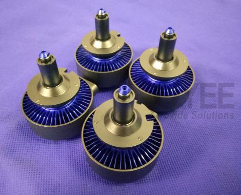
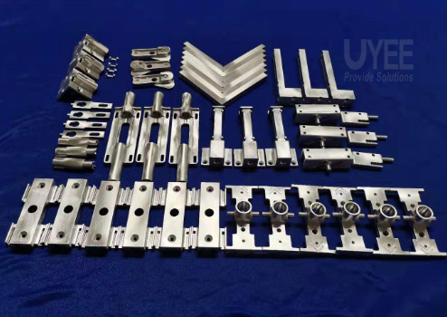
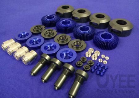
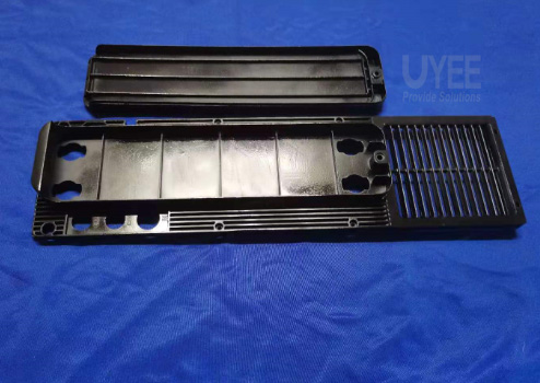
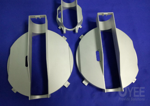
Assembly CNC Aluminum Prototype

How to Increase Aluminum CNC Machining Speed?

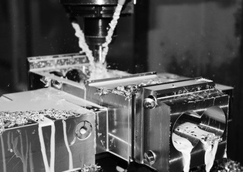
The best quality Aluminum machined parts and a better machine-friendliness of Aluminum makes it the number one metal choice for machining purposes. The properties of Aluminum make it easy to drill, mill, punch and cut and aluminum machining results in the parts which are durable, strong, and pleasant looking. Overall, Aluminum is the market’s most machinable metal.

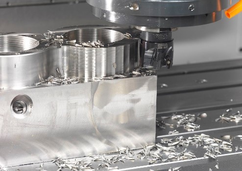
Still, there are specific problems involved with the easier machinability of Aluminium, making it far from being perfect. CNC aluminum prototypes face the most significant issue of lower speed due to various factors, including the stingy, long, and obstructive chips. This eventually results in rougher thread finishes, bad chip wrapping, and straightness and appearance issues.

The individuals involved in machining businesses, engineers, and metallurgy experts are also working rapidly on the solutions to enhance the CNC aluminum machining speed by enhancing the material quality, machining practices, choosing proper alloys, and other practices.
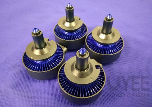
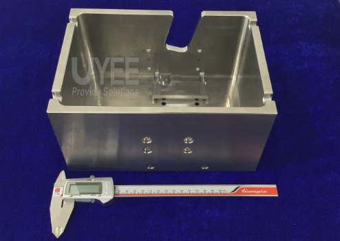
Assembly CNC Aluminum Prototype

Tips to increase CNC aluminum machining speed –

Are you getting the Aluminum machined parts from the processes involving Computer Numerical Control (CNC)? If so, you might face some recurring issues related to finishing the resultant aluminum prototype and parts.

The main difficulty that a CNC programmer overlooks daily is to recognize critical machining parameters like depth of cut, spindle speed, and feed rate. In older days, the beginning path of this task would be either a machining data handbook or the practice of leader machinists on the floor.

So, to get the super excellent outcomes, it is necessary to cover a lot of ground. It includes:-

  • Optimization of cost for material extraction.
  • Increase the life of tools.
  • Higher-quality finishing for the exterior.

CNC routers are used mainly with wood and acrylics, and they are sufficiently handy to control the needs of materials like aluminum. A crucial aspect of aluminum machining is modifying the step to accommodate its various features.

Follow all the mentioned tips to minimize the difficulties and generate high-quality Aluminum parts while maintaining a higher aluminum machining speed.

  1. Determine accurate feeds and speeds

The best combination of speeds and feeds for aluminum is a confined range with most of the metals than acrylics and woods. Cutting aluminum also requires a better spindle speed that might even shift the CNC machine’s outer limit.

  • Feed rates of not so good speed might result into rubbing and decrease the tool’s longer life.
  • Feed rates that are of good speed might impose a burden on the machine, causing some breakage.

Speeds and feeds will help you to accurately calculate the rate.

  1. Make use of Carbide-Coated Bits with smaller Diameter

As the higher RPMs are committed to cutting aluminum, high-speed steel and cobalt are not appropriate for the task. Carbide is a stiffer material, and thus proffering it is considered as a better solution.

Lesser diameter bits are also required by the speedier machine rates. The carbide’s stiffness is also a benefit as it saves from the possible tool deflection.

  1. Maintaining a stable Temperature

As Aluminum machined parts are unsafe due to more variations in the temperature, it is intolerable to produce the waste as the developed parts. Utilize the software and hardware capable of holding temperature at the right level. This eventually helps increase the speed of the CNC aluminum machining.

  1. Clear all the chips completely

Well, aluminum metal holds the factor of “stickiness,” and due to this, it is welded essentially to the tool, following in shoddy quality work and extra wear and tear on the machine.

Don’t depend only and completely on the dirt collector system and always check the machine thoroughly to be sure that the chips are entirely clear.

Spin a coolant mist or some other lubricant on the machine to decrease the tendency of the chip to stick.
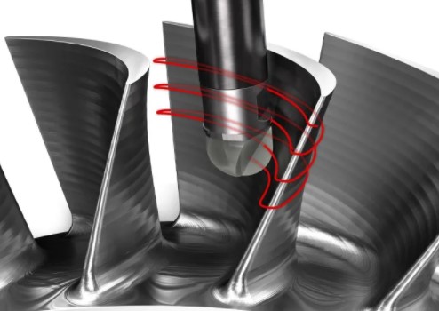
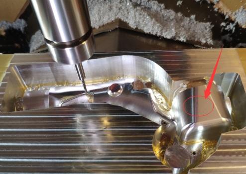
CNC milling programming path

  1. Move slow and steady

There’s a fascination to save the hour by making deeper cuts, but sometimes this approach might not succeed and fail by making it difficult to entirely clear the chips. Stick to the regular measures for enabling higher control and better access for chip removal.

  1. Decrease the number of Flutes

A major amount of Flutes might also increase the chip problem by causing them to get tightly collected. Set the utmost limit of 3 flutes with aluminium CNC machining. If the space rise between the cutting edge, escaping out will get easier for larger chips.

  1. Choose the proper cutting fluid or Coolant

Today’s cutting fluids come with a wide range of options. To meet the demands of new materials, cutting tools, and tool coatings, a slew of new coolants have been created.

When it comes to machining, the heat produced by friction at the tool-workpiece interface has a big impact on a lot of things. Tool wear and, as a result, tool life are greatly increased as the temperature at the contact zone rises.

Cutting fluids has some major functions including:

  • Cooling the work piece, tool and the chip
  • Reducing the friction and thus increasing the speed of aluminium CNC prototyping production.
  • Reducing the built up edge formation and chip welding
  • Preventing corrosion and rust
  • Flushing away the chips

Metal machining operations must strive to increase efficiency while lowering costs. This is achieved by machining at the fastest possible speed while preserving tool life, eliminating scrap, and delivering parts with the best possible surface quality. Both of these objectives can be met by ensuring proper cutting fluid selection and application.

Conclusion

The best speeds and feed for your project are influenced by a number of important factors. The method, material, fixturing, chip removal, and tool path form are among them.There is no such thing as a list of speeds and feeds that suits all. Every project is different, and it can take some trial and error to find the right environment. Finally, the aim is to create a component that fits your specifications. When you understand how each feedback influences the final result, fine-tuning the settings would be much easier.

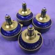
CNC milling

8 Tips Of CNC Machining Titanium

The popularity of Titanium alloys as a material for structural and other parts is growing exponentially. Since, titanium holds an incredible strength to weight ratio and resistance to corrosion, it has become a winning component all across the industry verticals like aerospace, automotive, and medical. Consumer product designers, industrial engineers and architects appreciate its material properties like-

  • Good machinability
  • Ductility
  • Surface treatment options
  • Recyclability

titanium machined Lidar device part

Why choose CNC machine titanium?

CNC machining titanium is always considered as one of the best manufacturing technique. It widely help industries in getting the most reasonable and exact titanium parts. It typically employs computerized controls and machine tools in order to eliminate the layers of material from a stock piece—commonly known as the blank or workpiece and produces a custom-designed part.

With custom titanium manufacturing, it helps you in expediting any production order in quantities. This process accepts the design and specification from the compatible software programs that contributes crucially in producing precise and consistent matched parts. One of the best part of CNC Machine Titanium is that it requires little maintenance services except cutting new implements occasionally.

You can connect with the best professionals for custom titanium manufacturing services who can work continuously to meet your demanding deadlines. Here some of these important tips of CNC Machining Titanium-

1.      Keep Temperatures Down

Since Titanium is a bad conductor of heat, most of the energy is produced during the cutting process. Such heat often leads to harmful impacts that can result into impulsive failure in tool. It can weaken your tool and lead to rubbing that generates even more heat.

Based on the constituents that you are incorporating, this can also be a risk of fire. However note that when your tools become dull, it could be expensive enough for you and may damage your work.

Along with that, poor heat dissipation can cause strain hardening, where in the edges of your work piece becomes tough and then it becomes difficult to give a cut. Such a hardening effect will trouble the speed pace where the cutting process is conducted. Therefore, you can incorporate coolant that can control the temperature and gradually keeps it down.

2.      Focus on making Your Surface Stable

Another effective way for adding strain on the tool is that you can bare it to the jarring and shock changes with a compulsion. Generally, this is quite an obvious thing to understand whenever it comes in and moves out of the material.

Now in order to make the surface stable, you will have to insert the tool directly inside the metal and then arc it privately to effortlessly penetrate the cut. Such an arc will not only accelerate the pressure but also makes the entrant less vibrating and help you slide into the same direction – anticlockwise or clockwise.

If you want that same result, consider a chamfer. A chamfer is a transitional or beveled edge used mainly to make a slanted surface. It contributes crucially in letting the tool to gradually penetrate instead of making any abruption. Such a tool helps you in easing the transition with limited application of force.

CNC milling

3.      Take care of Your Tools

It is very much important to incorporate a sharp tool for an effective cutting. And in that case, Titanium wins the show very quickly. However, you will have to inspect or watch these tools frequently and replace quickly in case of wear and tear.

Any dull or ineffective tool will ultimately increase the proportion of heat and wear out even faster than you can think of. If you stuck anywhere, contact the professionals for CNC Machining Titanium for the best results.

4.      Give some reasonable space to your tools

It is really quite imperative to give some space to your tools. For instance, if you are using a tool that has a smaller diameter, then it will help you in creating more exposure to coolant and air. This will permit the cut edge in spending reasonable time for cooling. Since it gives the metal time to breathe amidst the cut, it is called as an efficient technique for controlling the temperature.

5.      Try to reduce Galling

Naturally, Titanium amalgamates with the other materials quickly that can lead to rewelding and galling of the edge during the process of cutting. However, if you keep the heat down with the help of such sharp tools and effective lubricant, you will be able to control the effect of galling.

6.      Control Chipping

Edge chips happens when the metal pieces are cut, trodden and stick to the boundaries of the cutting tool. As more pieces build up on the cutting tool, this creates a negative impact on the performance. However, it can result into a more quickly damaged or a poorly cut tool. Therefore, it is advised to use a sharp tool and lubricant in order to reduce chipping.

  1.     Work holding

Titanium possesses the most desirable material properties and it acts more flexibly than other metals. Moreover, it requires a safe and secure grip on the Titanium work pieces and on the machine set up. So, the tip here is try to avoid the interrupted cuts and ensure that the tools works in a proper motion in contact with the work piece. Also, if you dwell into the drilled hole or hold the tool straight to a profiled wall, the tool will start running creating an excessive heat pressure. Further, it would result into hardening of the material.

  1.     Selecting a tool smaller than the pocket

Every tool requires clearance to allow for cooling. When mill a small pocket, the diameter of the tool must be less than 70% of the diameter of the pocket. If the clearance is less, the tool needs to be insulated from coolant and you will have to trap the chips to carry off the heat. In total, it helps in the creation of thick to thin chip.

What Can We Help You ?

Are you already thinking of availing Titanium milling service? We can definitely help you here. UYEE is a team of professionals who possess years of experience in delivering quality CNC machining services. To know more about what we do, get in touch with our experts at info@uyee-rapidprototype.com


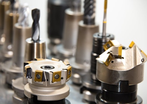
CNC Cutting Tools

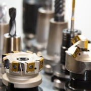
Selecting the Right Cutting Tools For CNC Aluminum Machining

Aluminum is the most commonly machined materials because most types of the material have outstanding machinability and are therefore widely used in manufacturing. As a result, competition for CNC Machined Aluminum can be fierce. Understanding the fundamentals of tool selection, running conditions, and advanced aluminum milling techniques will help machinists gain a competitive edge.

CNC Prototype Fitted

Why choose Aluminum for CNC machining?

Aluminum and its alloys need much less cutting force than steel, so the cutting edge of a milling tool experiences relatively low mechanical loading. Since aluminum has high thermal conductivity, the chips created when machining aluminum pass a significant amount of generated heat, resulting in significantly reduced thermal loading of the cutting edge. Because of these properties, Aluminum CNC machining requires extremely fast cutting speeds and feeds. However, this does not guarantee that machining aluminum will be as easy.

Material Properties

Aluminum is a highly malleable, workable, and lightweight metal. This material’s components can get used in virtually every industry. Furthermore, because of its low cost and versatility, aluminum has become a common material for prototypes.

Aluminum comes in two primary forms: cast and wrought. Wrought aluminum alloys are usually more robust, more costly, and contain fewer outside elements. Wrought aluminum is also more heat resistant than cast aluminum and more machinable.

Cast aluminum has a lower tensile strength but a higher degree of flexibility. It is less expensive than Wrought and has higher concentrations of outside elements (silicon, magnesium, etc.) in its alloys, making it more abrasive.

CNC Cutting Tools

Tool Geometry

There are coating options available for aluminum tooling, including the common gold-colored ZrN (Zirconium Nitride) and the lesser-known but highly effective TiB2 (Titanium Diboride). Uncoated tooling can also provide good machining results. However, knowing the correct flute count and helix angle for your process is the real secret to high-performance machining in aluminum.

  • Flute Count

End mills for aluminum are mainly available in two or three flute configurations. Higher flute counts would make it impossible to evacuate chips efficiently at the high speeds possible in aluminum. Because aluminum alloys leave a large chunk, and chip valleys on end mills get smaller with each additional flute.

End mills with two flutes have traditionally been the preferred alternative for aluminum. On the other hand, three flute end mills have proven to be more effective in many finishing operations, and with the right conditions, they can also act as routers. While much of the debate between two and three flute end mills for aluminum boils down to personal preference, the process, rigidity, and desired material removal rates may influence tool selection.

  • Helix Angles

The helix angle is the angle generated by the centerline of the instrument and a tangent straight line at the tip. Aluminum cutting tools generally have higher helix angles than standard end mills. Helix angles are typically 35°, 40°, or 45° specialized in aluminum. Variable helix tools are also available, and they are excellent for minimizing chatter and harmonics while increasing material removal speeds.

For conventional roughing and slotting applications, a helix angle of 35° or 40° is a reasonable option. A 45° helix angle is the preferred option for finishing. It is also the preferred choice for High-Efficiency Milling tools because the high helix angle wraps around the tool faster and produces a more aggressive cut.

Tooling Options

When machining aluminum, regular 2 or 3 flute tools will usually suffice. However, for some applications and system configurations, there are some additional tooling choices to consider for improved performance.

  • Chipbreaker Tooling

Efficient chip evacuation is one of the most critical factors to remember with CNC Machined Aluminum (and many other materials). It can evacuate chips reasonably well with standard 2-3 flute end mills operating at recommended speeds and feeds and with sufficient chip loads. Three flute chip breaker tooling, on the other hand, can be used at higher speeds and feed rates for even better efficiency. The offset chip breaker geometry produces more minor chips for optimum evacuation while maintaining a semi-finished board.

These tools are ideal for more specialized tools, such as High-Efficiency Milling, which is another essential tool for a good aluminum machining experience.

  • High Balance End Mills

High balance end mills get intended to improve efficiency in highly balanced machining centers capable of high RPMs and feed speeds. These tools are precision balanced and designed especially for high-velocity aluminum machining (up to 33,000 RPM).

We provide CNC Aluminum services with tools in traditional two flute styles and coolant-through three flute styles for reduced heat, improved chip evacuation, and faster material removal speeds. These methods, including chip breakers, are also ideal for High-Efficiency Milling tools.

Bottom Line

To summarize, milling aluminum is a simple process if done correctly! For good results, use an effective cutting technique and properly selected milling tools. Please note that the machinists play an important role in whole machining process .


CNC milling programming path

Typical Tips For Saving The Cost of CNC Prototyping?

CNC prototyping improves and advances year after year, becoming a little more complex as a result. As a result, keeping up with the dos and don’ts of component design can be difficult. However, lowering the cost of machined parts while enhancing functionality is still possible with a few simple changes to your component design or material selection.

CNC prototyping for lock system


How can I save the cost of CNC prototyping?

Based on a process designed to produce parts quickly, we use automation software to quote parts and highlight features that need design consideration. The program can detect features that are non-manufacturable at the outset (or are manufacturable but need additional tools and equipment). Still, it will also highlight areas that do not necessarily require modification but may increase the design’s overall machinability—corner pockets, etched text, thin walls, deep pockets and gaps, and complex geometries.

Here are several options to help you create more cost-effective machined pieces.

  1. Provide Relief to Corner Pockets

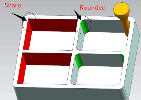
Consider the corners of a machined pocket—perhaps the inside of an electronics housing or a bracket used to hold the body of a rectangular part. One common design mistake is to leave the intersection of the vertical walls on those component features perfectly sharp. Consider machining a stainless steel box to house a set of baseball playing cards. Electrical discharge machining (EDM) or several flat plates bolted together are the only ways to achieve the perfectly square vertical corners needed to match those Babe Ruths and Hank Aarons. Both can be time-consuming and costly.

Instead, we’ll use the smallest end mill available to clean out the corners on one of our Prototype Company machining parts. It’s pretty sharp, but there’s only so much depth there. Most of the steel-cutting end mills in this size range have a maximum length of five times the cutter diameter, which is barely deep enough to accommodate your favorite center fielders. Prototyping with small end mills like this is often time-consuming and fragile, increasing your project’s cost due to additional milling time.

CNC milling programming path

Machining a gap in each corner of the pocket is a less expensive option. It gets rid of the pesky radius, leaving a U- or C-shaped clearance in its place. It also makes for much deeper pockets—by cutting a 0.25 in, (6.35mm) broad relief in each corner, technically sharp corners with depths of up to 1-1/4 in. (32mm) are possible. Using aluminum or even plastic instead of steel, pocket depths that are twice as deep as steel is possible. The best part is that building pockets lower part cost because larger end mills can get used, and it can improve material removal speeds accordingly.

  1. Deburr Edges Yourself

Another radius-related cost-cutting step is to avoid corner breaks. External component intersections are often smoothed with chamfers or corner radii to eliminate burrs and break sharp corners. It’s natural and usually even appropriate, but it can be costly. We provide automated deburring on metal parts, and plastics are supplied as-machined or with a sharp edge.

If the part design requires an edge split, we must use an additional tool (a ball end mill) to machine the corners with a 3D profiling motion. We usually run these tools at high rpm and extract tiny quantities of content, but it’s still a time-consuming process to go back and forth until each corner is smooth. Many consumers prefer to save money by deburring these parts themselves with a file, abrasive document, or a buffing wheel.

  1. Avoid Text Until Molding

Similarly, text engraving is an aesthetically pleasing yet time-consuming process that should get avoided if possible. A ball end mill gets used to trace whatever letters, numbers, and symbols get defined on the CAD model. It looks great and may be a legitimate requirement for your machined component. Still, it’s probably more suitable for injection-molded products, where the extra         CNC Prototype time gets amortized over higher part volumes. We have a minimum size of 0.90mm in metals and 0.51mm in plastics due to our tooling for metals vs. plastics.

  1. Be Cautious of Thin Walls and Features

Our standard tolerance for parts is +/- 0.005 in (0.13mm). Suppose you have a feature that is 0.020 in. (0.51mm) or smaller. In that case, our automated quoting system will highlight it as thin-wall geometry but bear in mind that it can still be machined so that the machined component can vary slightly from your original design. Thin walls of 0.020 in. or less are not only prone to breakage during the prototyping process, but they can also flex or warp afterward. Increase their size as much as your component design requires.

  1. Keep it Simple

Even if the corners are relieved, deep pockets are not permitted. Gussets or support systems can get used to support these workpieces and avoid stress-related movement, but these appear to increase machining costs. Keep it easy is the best advice for any Prototype Companies or machined component designer.

The same principle holds for overall component geometry. Don’t try to make parts do more than they need to. Maximizing material use can result in work holding or machining issues, raising costs. If the design becomes too complicated, consider breaking it down into different parts and assembling them with fasteners.

Nobody enjoys assembly costs or the complexity that comes with several components, but it might be the best solution for difficult-to-machine details if speed is a necessity. Sculptured surfaces, cavernous slots (think heatsinks), super deep holes (hydraulic manifolds), and threads are all popular Prototyping cost drivers that can eat into your project budget.

We hope these tips will help you save on the cost of CNC prototyping. Switching to a more machine-friendly or less costly material is one of the best ways to remain within budget (assuming it meets the requirements).

CNC Aluminum prototype machining

9 Tips When You Are Custom Milled Parts

Custom milling is simply known as CNC machining which includes CNC milling, CNC turning, EDM, etc —Due to the good speed of CAD modeling and the ease of online orders of global shipping, it is now convenient to create or order custom milled parts in a matter of days. Here are some pints to help you make the most of your CNC custom milled parts.

CNC Aluminum Parts

  1. Buy some good quality cutters

Don’t buy cheap, low-quality cutters. Get some decent blades from a well-known brand at a fair price. It will significantly differentiate the quality of the CNC machined prototype parts produced and remove a slew of needless issues that may arise using less expensive equipment. Carbide cutters, for example, can last longer. You’ll want to have a few different versions, such as 12″ and 14″ and so on. Wear your protection goggles because these cutters will shatter. It’s also an excellent deal to purchase a complete drill set.

  1. Purchase a high-quality vise, parallels, and a clamping kit.

Workholding is essential for holding the milled parts in place. You’ll need a high-quality vise that will last for several years. You don’t want your machined prototype part to go out of business.A good clamping kit will allow you to mount your vise to your table’s T-slots. Finally, invest in a good selection of parallels to hold the workpiece parallel or equally elevated for the cutting tool/spindle to move over.

  1. A coolant misting system is needed to prevent chip buildup.

There are two kinds of siphons: siphon-based and micro-drop. The siphon mechanism atomizes the coolant fully into an aerosol, which can be messy. The micro-drop device pressurizes the coolant, holding the coolant and air apart until they reach the tool’s tip. When the coolant reaches the workpiece with the micro-drop mechanism, it vaporizes. It’s a lot more effective and less messy. A successful misting device can aid in the prevention of chip buildup.

  1. Learn to use Manual Data Input (MDI)

Using the Manual Data Input (MDI), which gets accessed via the MDI keypad on your CNC machine’s control panel, will save you a lot of time and improve your productivity. It is easy to understand and will save you a lot of time. You can set some simple g-codes and change your X, Y, and Z coordinates, as well as shift your axes, and the computer will move fast once you’ve entered the details. The machine’s fast movement get referred to as “Rapids.” You want the cutter to go in the direction you want it to go.

  1. To improve accuracy, invest in a feeds and speeds calculator.

When making your cuts, accuracy is of the utmost importance. To ensure this, use a feeds and speeds calculator to ensure that your spindle speeds and feed rates are accurate from the start.

CNC Aluminum prototype machining

  1. Purchase a touch tool measuring kit to obtain precise Z-height measurements. Purchase an Edge Finder as well and use it to set your part zeros.

For precision, the computer must know where the tip of the tool is. The Touch Tool will tell your computer how long your instrument is and where the end is in Z. An Edge Finder is needed to set the X and Y positions. After inserting your material into your vise and inserting a tool into the spindle, you can use these measuring instruments to put your zeros.

  1. Tram your mill and vise for accurate cuts

Tram is the angle of your mill head concerning the table. A tram runs parallel to the x-axis and another parallel to the y-axis. When starting a new assignment, it is critical to inspect the tram on your mill. If you want precise cuts and the best finishes, your mill should be in tram mode. It is a fundamental skill that every machinist must master. Often, make sure your vise’s jaws are correctly get aligned with one axis or the other.

  1. Avoid using stainless steel. Starting with aluminum, brass, and mild steel is an excellent place to start.

You’re now able to start making some cuts. The first seven tips have now brought us to this stage, and we are getting prepared. You should stop using more rigid materials, such as stainless steel, for your first cuts while you’re just starting. It is critical to have confidence in using softer materials and mastering cuts while reducing the possibility of breaking or premature wear on your cutters. You will want high-quality finishes. The term “Mild Steel” can get used in a variety of places on the internet.

  1. Create a square block of aluminum material and a few sets of step jaws out of it.

Cut some slightly oversized pieces of material to act as vise jaws with your saw. Cut the stock somewhat more extensive than required. The following move would be to square these bricks. Squaring entails making a series of milling cuts until both sides are parallel or perpendicular to each other, resulting in a workpiece that is “square.”

After you’ve squared the stuff, you’ll cut it to size by milling it until it fits perfectly in your vise jaws. (You will need two square bits, one for each jaw.) The mounting holes should then be drilled and countersunk. Finally, mill a step down each jaw. You may use this step instead of parallels when inserting the material into the vise if you prefer.


industrial product design CAD model

What do You need To Know With Prototype Model Making?

A prototype is developed using the requirements before starting the coding or design process. By using a prototype, you can get an “actual look and feel” of the product. Prototyping is a very effective method for large systems or products for which there is no manual process to determine the requirements.

industrial product design CAD model

What is the Prototype model making?

The prototype model making is one of the widely used Software Development Life Cycle Models (SDLC models).you can use this model if your customer does not know the project requirements beforehand. In such cases, you can develop, test, and refine your prototype model as per customer feedback till a final acceptable prototype is made to lay the foundation for developing the final product.

What are the different types of Prototyping?

 There are mainly four types of Prototype model available:

1Rapid Throwaway Prototyping

 This Prototyping method helps you explore ideas and get customer feedback, and the developed prototype needs not be a part of the prototype accepted by the customer.

2Incremental Prototyping

 The incremental Prototyping method is when the expected product is broken down into small bits of prototypes, and then you have to develop them individually.

3The evolutionary Prototyping

 In his method, the prototype developed initially is first refined based on customer feedback until the customer accepts it.

4Extreme Prototyping

 The powerful prototyping method makes the project delivery robust and fast. In this method, the entire development team is centralized on product deliveries instead of finding specifications and adding unnecessitated features.

rapid prototype model making

Here are some essential things to think about while prototyping:

Industrial design prototyping

STP files are used to build setup and part development. At the same time, it can convert most native CAD. When using the STP format outside of the native program, problems may occur, resulting in build failures or missing features—sending in your CAD. The STP format reduces the possibility of errors.

Multiple Shells or Unshared Edges

Multiple shells and unshared edges typically indicate an uneven topography, implying that surfaces can overlap or get disconnected from one another. If several shells and unshared edges get left in the file, the component may not build correctly, resulting in missing features or building in separate parts.

 Verifying the Unit of Measurement

Make a note of the unit of measurement that your file was get constructed. Harvest is an inch-based program that can convert files from metric units. Noting the initial division of measure, on the other hand, would save time and minimize possible errors.

 Designing for the Process

 Every industrial design prototyping process has its quirks and design constraints (tolerance, feature definition, material properties, etc.). These distinct process/material properties should get considered when developing the model component to incorporate offsets, variances, and adjustments into the CAD model (s).

Choosing Price over Process

 Although pricing is always a factor when prototyping, the primary focus should always be on optimizing functionality and achieving the desired goals. Choosing the cheapest option between processes can result in a prototype that does not work correctly or meets your requirements.

Detailed Instructions

 Explaining your basic prototype requirements for fit, shape, finish, and functionality will help a harvest project manager determine the best choice for manufacturing your rapid prototyping model. Whether it’s water resistance, surface smoothness, or painted display model aesthetics, the more specific you can be, the more we’ll be able to refine our processes/post-processes.

Small Features/Thin walls

 There is a minimum feature size for each process and content. It can range from.010′′ to.030′′. Understanding this constraint will help you select the best choices or modify the CAD model(s) to achieve the desired result.

Tolerance Variance

 Since industrial design prototyping processes are essentially free-form production systems, they have lower tolerance control than conventional manufacturing methods such as CNC machining and injection molding. These processes are still accurate to thousands of an inch, but some designs (such as interference fits and line-to-line designs) must account for minor dimensional variance.

Application Consideration

 When selecting a method or material for your prototype, keep the application at the forefront of your mind. It is essential that you thoroughly clarify how the prototype will get used so that a manufacturing project manager can provide reliable assistance. Although your concept may be well suited to a specific production material or process, the implementation of your rapid prototyping model may not be well appropriate to specific 3D printing processes and materials.

Conclusion

 We hope the above-mentioned tips in this article will help you in making a prototype model for your products. If you need your prototype in a few days or a few weeks, you must take particular care not to rush the design/CAD modeling process and make needless errors. Taking the time to review your final design for possible issues and go over these tips stop you from making an expensive mistake.


CNC Programming

How to Save Cost with CNC Rapid Prototyping Process?

Materials, design, finishes, quantity, and turnaround time are all factors that can influence the cost of CNC Machining Parts. The most significant aspect is usually the amount of time it takes to machine your pieces. It can significantly impact costs more than the cost of materials, setup time, or finishing form.

The materials you choose and the nature of your parts have a significant impact on machining time. Part geometry and tolerances also influence the number and type of machines required and the machinists’ ability levels needed to operate them, affecting costs.

How to save money with a CNC Rapid prototyping project?

Here are ten ideas to help you make more cost-effective decisions for your next CNC Prototyping project.

  1. Optimize Materials Choices

Materials have an effect on cost both as raw materials and in terms of machinability. Although the price of raw material may be low, if it is difficult to machine, it may end up costing more than a slightly more expensive raw material that is easier for the device. In general, softer materials are simpler to cut, requiring less machine time and allowing less costly machines. Hazardous materials that necessitate extra safety measures may also boost production costs.

  2. Choose Quantity and Turnaround Time Tradeoffs

The cost per unit is directly affected by how many companies a CNC milling machine produces: more significant amounts decrease that number, even though the total overall cost is higher. Prototype machining is usually most cost-effective at charges for those big heavy parts. Prices are also affected by how quickly you want parts shipped: parts delivered in a few weeks would be less costly than pieces offered in two or three days.

3. Evaluate Finishes Carefully

Surface finishing and other procedures, such as heat treatments, advanced coatings, and anodizing, increase project costs and must be carefully considered. Multiple finishing processes or surface finish forms on a single part add processing steps and thus expense.

4. Avoid Complex Part Geometry

The dimensions of a component, including size and complexity, have a significant impact on cost. Larger parts necessitate more content. Complex, highly detailed features necessitate multiple processes and require various devices, raising the price of programming, fixturing, and setup. Some complex parts, such as those that need operations on various faces, may be less costly to manufacture if constructed as separate components joined together after machining.

5. Avoid Thin Walls

Some fragile walls — sometimes described as less than 0.794mm (1/32 in.) — are not appropriate for Prototype machining. Thin walls can cause distortion, making it challenging to keep tolerances. They can also cause chatter, causing machine speeds to slow. Both incur extra costs in terms of system and operator time. Other fabrication processes, such as sheet metal fabrication, could be more cost-effective for building walls thinner than this minimum.

6. Minimize Internal Cavities

Parts with large internal cavities, also known as deep pockets, are an excellent example of how component geometry influences cost in machining time and material quantities. These designs can necessitate several machining hours to remove enough material to build the cavities, resulting in waste and difficulty eliminating chips. The long, thin cutting tools needed to make these cavities are prone to breaking. A good rule is to keep the part length to no more than four times the part’s depth.

7. Retain Rounded Internal Corners

Enable machining tools to do what they already do automatically to avoid slowing them down. Tools like milling cutters and end mills leave rounded internal corners by default. The wider the corner’s radius, the less material the tool must extract, resulting in fewer passes. Narrow inside corner radii with length-to-diameter ratios greater than 3:1 necessitate further passes and special small devices, increasing machining time and necessitating tool changes. Maintaining the same radii for all internal corners can also minimize machining time and tool adjustments.

CNC Programming

8. Minimize Tight Tolerances

Tight tolerances may not get needed on every design’s surface, and having too many unnecessary ones raises the component’s overall cost. Typically, numerical callouts only get required for textures and features that are entirely essential to a component’s operation, such as interacting with others. Less critical elements can get machined to +/- 0.127mm (+/- 0.005 in.) tolerance.

9. Use Standard Drill and Tap Hole Sizes

A design that employs standard tap hole and drill sizes save money in several ways. Tap size and tread depth can also raise costs for tap holes. Threaded holes smaller than 2-56 in. need hand clicking, which adds time and labor costs, and should be avoided. Standard tap sizes, such as the more common 4-40 taps, are typically more readily available than 3-48 fixtures, for example. Threads three times the hole’s diameter are a reasonable rule of thumb, and even smaller ratios are preferable—tapping time increases when threads are too long and tap breakage occurs.

Using standard number, letter, or fractional drill sizes for drilling will save machine time by removing the need for reamers or end mills to finish holes to non-standard sizes. Standard sizes are usually fractions such as 1/4 in. or 1/8 in., or millimeters measured in whole numbers such as 2mm or 1mm.

tapping hole

10. Ensure Design Accuracy

Consulting an experienced machinist or engineer during the design process to check the accuracy of your CAD drawings may cost more upfront, but it will save you a lot of money in the long run. Incomplete or incorrect drawings will cause your component to get manufactured twice to get what you want, adding time and expense to your project.

Similarly, consulting a professional CNC manufacturer during the design process will help you avoid manufacturing parts that are too costly or difficult to machine. Instead, this will assist you in designing a component that is both practical and cost-effective to produce.


rapid prototype model for product design

How much do you know about Rapid Prototyping Services?

Rapid prototyping entails specialized manufacturing methods to create high-quality physical models of a 3D design concept. Prototypes may get used to upgrade designs as stepping stones to total production or for engineering tests. They get designed to be cost-effective and straightforward, with no investment in complex tooling required. Many customers need a physical part to get produced promptly to validate a design or capitalize on a brief sales opportunity.

It is a set of methods used to generate a model of a part from CAD data rapidly. The component can get built using CNC milling technology, 3D printing, or additive layer manufacturing.

  • CNC milling technology – CNC machining is very effective in Prototype manufacturing from various materials such as metal, wood, and plastic. For now more and more people prefer this process to develop their new products.
  • 3D printing – This is an additive manufacturing process that produces functional prototypes using CAD data and 3D printers. The most of advantage of this process is without the structure limited on the part.
  • Additive layer manufacturing – Laminated object manufacturing and solid ground curing are two other additive manufacturing processes. It’s new and modern manufacturing way .

rapid prototype model for product design

What are the Advantages of Rapid Prototyping?

Whether you are an engineer, industrial designer, or part of a product development team, rapid prototyping services will provide you with many benefits, including:

  • The ability to quickly explore and cost-effectively realize concepts. Quick turnaround times and low costs enable teams to progress far beyond the visualization of an idea, making it easier to understand the physical world’s properties and design.
  • Reiterate designs and incorporate changes that allow for improved product evaluation and functional testing. This iterative approach serves as a road map for designing and refining the final product before releasing it to the market, ensuring that the client’s design is optimized and error-free.
  • Show ideas concisely and successfully. Rapid prototyping transforms thoughts, pictures, and concepts from a notion or two-dimensional visual into tangible goods that customers, colleagues, and collaborators can hold and see in action.
  • The capability of thoroughly testing and refining a concept. The ability to mitigate design flaws with small-volume rapid Prototype manufacturing aids in the elimination of expensive design flaws that may not be apparent during an early evaluation.
  • By eliminating the need for setup and tooling, one can save time and money by using rapid prototype services. Because they can use the same equipment to create different prototypes with different properties and materials, overall costs and turnaround time is minimum.

What are the Disadvantages of Rapid Prototyping?

There are a few drawbacks to using rapid prototyping services that we should consider. Here is the list of few disadvantages of Rapid prototyping:

  • Sometimes prototype cannot present exactly the performance of the end product.
  • Issues with matching strength and surface finish using 3D printing technology.
  • Additional upfront costs
  • Some rapid prototyping processes are not cost-effective.
  • Skilled labor is required to create a perfect model according to the product design.
  • Materials available for use are limited.
  • It could also lead to insufficient analysis.

What are the different types of Rapid Prototyping Services?

CNC Machining

CNC machining is perfect for producing high-quality rapid prototypes out of plastic or metal without the need for costly tooling. Components will have tighter tolerances and better surface finishes than those made by other prototype services. Also, companies can machine all of the features required for a fully functional portion, such as tapped and threaded holes and exactly flat surfaces and all kinds of finished requirements .

For all CNC needs, companies have over 30 CNC mills, lathes, and EDM machines on-site. They also have a multilingual support team to ensure that the product development journey is as easy and stress-free as possible.

Metal 3D Printing

Metal 3D printing is perfect for creating complicated shapes that are light in weight but strong in strength. Complex tooling is not required, and it can print parts in hours rather than days or weeks.

To develop completely dense sections for maximum performance, companies use a cutting-edge Renishaw AM250 printer. Equally important, they have in-house specialist technicians who can provide clients with an unrivaled engineering knowledge level to ensure clients get the best quality finished product.

Vacuum Casting

Polyurethane vacuum casting molds should produce up to 30 high-fidelity copies of the original master pattern. Parts may be overloaded in different materials and molded in various resins, including engineering-grade plastics. It is suitable for low volume production plastic, rubber products with fast turn around .  And also ,it can get saved much more cost to compare with plastic injection molding , so this is a big advantage .

Companies specialize in producing high-quality cast copies from master patterns. The client will benefit not only from companies’ outstanding attention to detail, but they also offer a complete suite of finishing services to take part up to showroom quality.

SLA Prototype

SLA is one of the first plastic 3D printing or additive manufacturing processes. These techniques are not only rapid, but they also allow you to create complicated internal features that are difficult to produce using traditional manufacturing methods. To make master patterns for vacuum casting molds, companies use SLA. It is best suited for producing small quantities of finished parts or prototypes.

CONCLUSION

With technological innovations, it is high time to adopt the latest manufacturing, rapid prototyping to save time, money, and the effort to create the new product. This type of technology is essential during new product development process and innovations.

CNC Machining

How Much Do You Know For CNC Machining Services?

Organizations today are simplifying the product development process with CNC machining services. It helps speed up manufacturing machined parts with the highest degree of quality and accuracy, ensuring consistent product quality, increased production speed, and product efficiency. CNC machining  include a range of complex processes like grinding, turning, routing, milling, punching, and lathing. In this article, we will tell you what exactly CNC machining is and its capabilities in detail.

What is ​High Precision CNC Machining?

In Computer Numeric Controlled (CNC) Machining, the technology uses fast, repeatable, and programmable systems to make parts more effective.  It signifies one of two methods like 3D printing technology and FDM to generate prototypes from a digital software file. The operation is, therefore, more straightforward since the CNC controllers control the CNC devices. The method allows computers to produce objects with complicated geometries that may be impossible to achieve with a manual process. Replacing traditional instruments and expertise with high-precision machines will help factories save time and resources.

CNC Machining

What are the benefits of CNC machining?

CNC machining is a subtractive production technique that uses computerized equipment to extract surplus content from the block and complete tasks using the CNC system and its tools. These are the advantages of CNC machining services:

  1. The fully automated operation results in reduced overhead costs.
  2. High precision, resistance, accuracy, and dimensions;
  3. It can handle accelerated prototyping with low to high volume requirements.
  4. A more simplified method of development

The CNC Machining Process:

This production method is a fully integrated machine that uses computer-aided manufacturing (CAM) software and computer-aided design (CAD). For components with a simplified architecture, the user may explicitly input command programs to the computer. However, for more complex structures, a CAM or CAD drawing must first be created and inserted into the device. Alternatively, use coordinate measurement machines (CMMs) to map the configuration directions to the device physically. The program would automatically build and provide the necessary steps for the system to produce the output.

There is less space for error since the computer would follow the letter’s instructions to produce the object. What’s much cooler is that this operation is easily repeatable, allowing the manufacture of similar parts more quickly. Previous applications of CNC machines are sluggish and are used only for high-volume processing. Now our technology has advanced considerably. Using complex technologies and tools now enables the direct introduction of computer-generated models into the application to make the operation much quicker. It also makes the use of low-volume CNC machining facilities to be more economical and practical.

Different Capabilities of CNC Machining:

CNC machining facilities to customers provide the following service of CNC machined parts from rapid prototyping to the manufacturing of parts and tools and the manufacture of end-use parts.

CNC Milling

It is the most traditional method that starts from a solid piece of raw material. This material forms by a CNC milling cutter operating in a circular motion. CNC milling machines can make parts of any shape, from primary keys to complicated parts, and can be horizontally or vertically aligned.

CNC Turning

This technology is a quick and fast-repeatable device that uses a lathe to extract excess material from a block by making grooves, gaps, and cuts. It uses a lathe or CNC spinning core that rotates at high speed as the cutting tool shifts in a rotating axis.

CNC Drilling

It is a cutting mechanism in which the block gets set and aligned with the cutting center as the tool rotates to make a circular hole.

CNC Milling and Turning

It is a fusion of two machining methods in which both the cutting tool and the workpiece rotate to create a component with a unique shape—the CNC computer design to perform several tasks in a short turn-around period.

Materials for CNC Machining Services

CNC machining facilities are the most cost-effective way of making a component or a prototype. There are several ways this machining method can make out of a complicated design and diverse materials. Companies ensure that the finest raw materials get used to producing a variety of goods with a high degree of integrity. Here are some of the components used by the Company for CNC Machining products.

  • Copper
  • Aluminum
  • Titanium
  • Polycarbonate
  • Stainless Steel
  • ABS
  • PMMA/Acrylic
  • Magnesium
  • Brass
  • Nylon

Machining Companies can also accommodate other fabrics of your choosing. With your CNC designs, companies will produce prototypes, limited batch models, and low-volume manufacturing of finished components.The following factors influence the entire CNC machining process:

  • Blade angle
  • Coolant
  • Cutting parameters
  • Speed and feed
  • Machine tool
  • Material

CNC machining is a subtractive production technique that uses computerized equipment to extract surplus content from the block and complete tasks using CNC machining. Make sure to choose the state-of-the-art CNC machined parts facility to increase your product’s sales and quality.


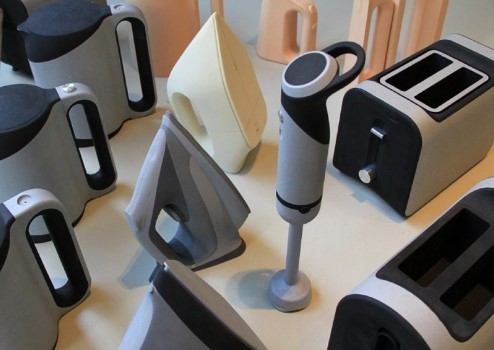
CNC Plastic Prototype for kitchen deivce

CNC Prototype Is Critical to The Product Development Process

Nowadays, everybody agrees that time is the key to New Product Growth. Marketing comes up with plans, Management signs off, and, of course, Engineering and Manufacturing departments left holding a bag to design, prototype, and produce the product. And, of course, it was due yesterday. This article will discuss how CNC Prototype is critical to the product development process.

CNC prototyping for lock system

What is Prototyping for Product Development?

Product development is a complex task for many organizations. That is why businesses are looking for new opportunities that will make the product production process more successful. The job of prototyping in product production is essential since the concept tested at this point. This stage is where the design that appears in the imaginary dimension taken into the process.

What is Rapid Prototyping in Product Development?

Rapid prototyping is a vital component of the design phase of product creation, and its benefits have been well established for years. A full-scale model from a designed concept can expose defects or show the potential for the prototype’s challenges before starting a 0-scale production.

Testing and testing a concept is a critical step in developing a smart, creative product. Rapid prototyping reduces production time by allowing the prototype to be corrected early in the process. By giving customers in infrastructure, production, marketing, and buying teams an early look at the product in the design stages, Customers can identify improvements, revisions, and errors that can get repaired – quickly and cheaply.

In the past, the conventional way of prototyping involves clay, wood, and other materials to make a mock-up, manufacturing, and other materials to use wire and duct tapes. Rapid prototyping services have implemented CNC, 3D printing, SLA, SLS, and several other manufacturing techniques.

Why do I use a CNC prototype for product development?

Not everybody in the Modern Product Development chain understands the complexities of ensuring that a new concept will achieve specifications at the right price and lead time. It’s just half the fight to put the strategy together. Another part of the puzzle is to find someone to do it. If it’s Stainless Steel, Aluminum, Carbon Steel, or Polymers, you’ll need to visit a professional CNC machine shop. CNC machines can shape your design from various metals, including aluminum, brass, copper, steel, and titanium. This method even hones softer, more readily machined components such as foam, fiberglass, or wood.

Also, CNC can be used to build constructive models of casting wax for the manufacture of molds. Traditional methods used by CNC systems include drills, lathes, and milling assemblies. New developments often integrated into CNC include ultrasonics and electron beams.

CNC Plastic Prototype for kitchen deivce

Here are some of the noticeable benefits of CNC Prototype Machining for product development:

  • Enhanced Capabilities: One of the most remarkable reasons for making a prototype made with a CNC computer is to produce model parts or components with incredible precision when used in combination with specialized CAM or CAD tools. Something that cannot get achieved with a manually operated machine.
  • Friendly Material: Another advantage of CNC machining for protocols over other methods is that the producer can use various products. Irrespective of whether you require a sample made of plastic or metal, CNC machining will accommodate it.
  • Fast Turnaround: CNC machines can run around the clock 365 days a year, unlike humans that have to take breaks. The manufacturer does not use this kind of equipment for repair and upgrade purposes.
  • Controlled Precision: For CNC prototyping, computer software, typically in CAD, produces a three-dimensional representation of the completed element or object’s looks and functions. After the design gets fed into the machine’s computer, the prototype gets built accordingly. Since the system executes computer program instructions, it makes controlled motions to generate accurate models.
  • Scalability: In addition to generating precision protocols, a CNC system can produce hundreds or thousands of replicated items. After evaluating the model, the engineers will make any required modifications. The operator also supplies the new knowledge to the software program, informing the computer how to make the appropriate amount of finished goods with extreme precision.
  • Minor Human Involvement: The CNC computer performs a lot of work. The only human intervention comes from a professional technician who maintains that it performs optimally during development.

CNC Prototype Machining is an innovative process that continues to evolve. It does not only refer to metals, but you can also use CNC for plastics. The most significant advantage of using CNC for prototyping is checking the strength and integrity of the components. CNC is also very well integrated with other manufacturing techniques, such as welding and bonding.

All in all, finding a shop to do  Prototype CNC  is a very critical aspect of the New Product Development process. It should not be focused solely on lead time and costs. Ensure that you ask the correct questions and that the supplier will meet the final target.

CNC aluminum prototype with light sandblasted finishing

Why Is CNC Aluminum Prototype Widely Used?

Aluminum is one of the most common material options for CNC machining and prototyping due to its attractive physical properties. The metal is reliable, making it suitable for mechanical components, and the oxidized outer layer of Aluminum is resistant to corrosion by the elements. Unlike many other metals with comparable chemical properties, aluminum provides outstanding machinability: It can successfully penetrate many of its grades by cutting equipment, chipping quickly, and being relatively easy to mold. Aluminum can also be machined more than three times faster than iron or steel.

Here we will discuss some of the critical benefits of CNC Aluminum Prototype and why it is one of the most common prototyping and manufacturing processes, along with some alternatives for aluminum.

 What are the benefits of CNC Machining for Prototyping?

 CNC machining has a range of benefits over 3D printing and other prototyping methods discussed in this article and some drawbacks. One of the main advantages of using CNC machining to make prototypes—Especially for parts finally formed by injection molding—is that CNC machining creates prototypes made of solid materials, unlike 3D printing. It indicates that the CNC machined components’ mechanical properties are very similar to those of the injection molded parts.

It can produce CNC machined parts designs with outstanding surface finishes. Depending on the material chosen and depending on the post-processing processes used, It may leave CNC machine sections as machined, beaded, anodized, powder-coated, sanded with varying grits down to a polished surface, or chrome-plated.

CNC aluminum prototype with light sandblasted finishing

So, why CNC Aluminum Prototype is widely used?

 Here are some of the reason why CNC Aluminum Prototype is used :

 Custom Finishing

 Aluminum can be mold to suit the customer’s needs after finishing. You can make it seem like the most beautiful tradition by doing specific stuff. Aluminum CNC pieces can get plated with different colors as per the specifications. Three of the colors you can try are purple, blue, and green.

CNC aluminum machining is subject to various improvements, particularly in the design and requirements, which allow it to make a quick transition by beginning a newly reviewed and accepted program.

 Machinability

One of the critical reasons why engineers prefer aluminum for their machined components is because, very literally, the material is easy to machine. Although Aluminum CNC Machining would benefit the part’s equipment maker, it also has significant advantages for the corporation buying the piece and the end-user who would purchase it.

Since aluminum chips are simple and easy to mold, they can be cut easily and precisely using CNC machine tools. It has some significant consequences: firstly, the machining job’s short timeframe makes the operation easier (because the machine and less running time need less energy from the device itself). Secondly, good machinability means less deformation of the component as the cutting tool moves through the workpiece.

 Electrical conductivity

Pure aluminum metal has an electrical conductivity of approximately 37.7 million siemens per meter at normal room temperature. Aluminum alloys can have lower conductivity, but aluminum materials are considerably more conductive than other stainless steel alternatives. Due to their electrical conductivity, parts after Aluminum CNC Machining can be used for creating electrical components.

Easy Machining

 The other positive thing about the Aluminum prototype is that products can get conveniently created by punching, folding, and drilling. You may use it to shape the different shapes of the parts as required. The power used in the machining of aluminum is much smaller than that used in steel.

 Anodization potential

Machined aluminum parts are widespread in the consumer electronics industry, not only because of the strength and weight requirements but also because of essential esthetic considerations. As well as being receptive to paints and stains, you can treat aluminum with anodization to thicken the protective outer layer of the Aluminum.

Easily Bendable

 One positive thing about using the CNC machining process for manufacturing aluminum CNC parts is to bend them quickly. In comparison to steel, the machine can rapidly turn the aluminum material during the machining process. The thickness of this material can allow proper use of the different molding methods. The easiest way to do this is by pressing and grinding several shapes of aluminum CNC pieces quickly.

 Alternatives to aluminum in CNC machining

Businesses may, for any variety of reasons, pursue alternatives to aluminum for CNC machining. Overall, the metal has a few weaknesses: the oxide coating will destroy tooling and is typically more costly than substitutes such as steel, partially due to aluminum manufacturing’s high energy costs. Here are several possible machining alternatives to aluminum, focusing on their distinctions and similarity to common silver-gray metals.

  • Steel & stainless steel
  • Titanium
  • Magnesium
  • Brass
  • Copper

Thanks to the  CNC  machining, it is now effortless to come up with aluminum parts. The accuracy you get when removing those bits is the key reason many consider CNC Aluminum Prototype.

titanium machined Lidar device part

How To Improve the Titanium Machining Technology?

Titanium offers a unique property due to stiffness, outstanding corrosion resistance, toughness, low density, and excellent corrosion resistance. People who have seen a lathe machine or machining center know that cutting titanium sets complex machining demands. Titanium has several properties that make it a popular choice for aerospace and medical tools, but the same features may cause nervous breakdowns for machine operators. Using the right blend of application knowledge and tooling can help you correctly machine even the gnarliest titanium. Today, we will discuss the most important tips to keep in mind whenever you are titanium CNC machining.

Titanium CNC Machining

So, why is matching titanium a challenge?

Titanium has metallurgical characteristics and properties that make machining more challenging than other metals like cast iron and stainless steel. Titanium is an insulator by nature, the heat during machining stays near the cutting machine, blunting the tool, which creates more heat, and the process continues until the device fails. Another factor that makes titanium difficult for machining is that it is prone to work hardening. As titanium is cut, it becomes hard and even more abrasive to tooling. These are some of the challenges while machining titanium.

What are different types of titanium alloys?

Titanium alloys are known as a mixture of titanium and other elements. These alloys have very high tensile strength and toughness. Titanium is mixed with other parts to provide additional strength, flexibility, and malleability. Titanium alloys are used as various components like turbine blades and bio-materials. Different Titanium alloys come with their own unique set of properties and features.

Here are different types of Titanium alloys:

Pure titanium – Pure titanium is the easiest type of titanium with no alloying elements.

Alpha alloys – Alpha titanium alloys contain aluminum, oxygen, and/or nitrogen.

Beta alloys – Beta titanium alloys contain molybdenum, iron, vanadium, chromium, and manganese.

Mixed alloy – This is the mix of both alpha and beta Titanium alloys.

A glance at the evolution of Titanium Machining:

Around 15 years ago, titanium machining was a challenging and nasty job. Back then, titanium manufacturers were cutting blind and manufacturing parts through trial and error methods. Using hard metal techniques resulted in a costly process, demanded constant monitoring, and produced unpredictable outcomes. Today, end mills have perfect grinds and well-engineered geometries that manufacturers can cut hard materials like titanium without chipping or breaking tools.

Additionally, an adaptive tool from CAM software helps in achieving the steady and productive cutting of material. Another transformation in Titanium CNC machining is additive manufacturing technology, due to which high-torque is no longer required for rough milling, leaving only finishing operations for conventional machines.

titanium machined Lidar device part

Here are some tips for Titanium CNC machining:

Eliminate primary failure modes

 Choose a rake cutting tool with a rigid substrate and hard coating to avoid overheating. Also, a small T-land on the device’s cutting edge can help improve the tool’s functioning. However, avoid overdoing it as titanium is challenging and needs a sharp instrument.

Push the heat into the chip 

During machining Titanium, the low thermal conductivity traps heat that wreaks havoc on cutting tools. If your machine can handle the additional load, increase the feed rate to push some of the heat into the chip to make the machining tools last longer.

Increase coolant concentration

When cutting titanium, you need to maintain the copious flow of clean cutting fluid. To achieve this, increase the coolant concentration to 10 percent or more. Next, install a high-pressure pump of at least 500 psi to blast chips. Always, always use coolant-fed cutting tools to avoid catastrophic re-cutting of chips.

Choose the right tool

Invest in a high-performance machine tool if you want to achieve success in machining titanium. The high speed of the device can accelerate a chemical reaction between the chip and the tool material. Also, keep in mind that the tool should have good hardness and not react with titanium.

Be strategic

Plan and optimize the titanium machined parts process in advance. Analyze all of the part features, tall and thin walls, and hard-to-machine parts. Choose the right cutters, set the correct feeds and speeds, and generate code that meets the requirement analyzed before.

Titanium machining is not an easy task, but the material properties and usage mean that it is here to stay. As the use of titanium and its alloys continue to grow, more machinists will be dealing with titanium milling in the coming years. All you need to create a perfect blend of heat management, appropriate chip evacuation, correct coating to ensure success in machining titanium parts.