How to Save Cost with CNC Rapid Prototyping Process?
Materials, design, finishes, quantity, and turnaround time are all factors that can influence the cost of CNC Machining Parts. The most significant aspect is usually the amount of time it takes to machine your pieces. It can significantly impact costs more than the cost of materials, setup time, or finishing form.
The materials you choose and the nature of your parts have a significant impact on machining time. Part geometry and tolerances also influence the number and type of machines required and the machinists’ ability levels needed to operate them, affecting costs.
How to save money with a CNC Rapid prototyping project?
Here are ten ideas to help you make more cost-effective decisions for your next CNC Prototyping project.
1. Optimize Materials Choices
Materials have an effect on cost both as raw materials and in terms of machinability. Although the price of raw material may be low, if it is difficult to machine, it may end up costing more than a slightly more expensive raw material that is easier for the device. In general, softer materials are simpler to cut, requiring less machine time and allowing less costly machines. Hazardous materials that necessitate extra safety measures may also boost production costs.
2. Choose Quantity and Turnaround Time Tradeoffs
The cost per unit is directly affected by how many companies a CNC milling machine produces: more significant amounts decrease that number, even though the total overall cost is higher. Prototype machining is usually most cost-effective at charges for those big heavy parts. Prices are also affected by how quickly you want parts shipped: parts delivered in a few weeks would be less costly than pieces offered in two or three days.
3. Evaluate Finishes Carefully
Surface finishing and other procedures, such as heat treatments, advanced coatings, and anodizing, increase project costs and must be carefully considered. Multiple finishing processes or surface finish forms on a single part add processing steps and thus expense.
4. Avoid Complex Part Geometry
The dimensions of a component, including size and complexity, have a significant impact on cost. Larger parts necessitate more content. Complex, highly detailed features necessitate multiple processes and require various devices, raising the price of programming, fixturing, and setup. Some complex parts, such as those that need operations on various faces, may be less costly to manufacture if constructed as separate components joined together after machining.
5. Avoid Thin Walls
Some fragile walls — sometimes described as less than 0.794mm (1/32 in.) — are not appropriate for Prototype machining. Thin walls can cause distortion, making it challenging to keep tolerances. They can also cause chatter, causing machine speeds to slow. Both incur extra costs in terms of system and operator time. Other fabrication processes, such as sheet metal fabrication, could be more cost-effective for building walls thinner than this minimum.
6. Minimize Internal Cavities
Parts with large internal cavities, also known as deep pockets, are an excellent example of how component geometry influences cost in machining time and material quantities. These designs can necessitate several machining hours to remove enough material to build the cavities, resulting in waste and difficulty eliminating chips. The long, thin cutting tools needed to make these cavities are prone to breaking. A good rule is to keep the part length to no more than four times the part’s depth.
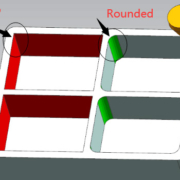
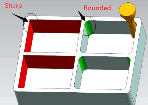
7. Retain Rounded Internal Corners
Enable machining tools to do what they already do automatically to avoid slowing them down. Tools like milling cutters and end mills leave rounded internal corners by default. The wider the corner’s radius, the less material the tool must extract, resulting in fewer passes. Narrow inside corner radii with length-to-diameter ratios greater than 3:1 necessitate further passes and special small devices, increasing machining time and necessitating tool changes. Maintaining the same radii for all internal corners can also minimize machining time and tool adjustments.
8. Minimize Tight Tolerances
Tight tolerances may not get needed on every design’s surface, and having too many unnecessary ones raises the component’s overall cost. Typically, numerical callouts only get required for textures and features that are entirely essential to a component’s operation, such as interacting with others. Less critical elements can get machined to +/- 0.127mm (+/- 0.005 in.) tolerance.
9. Use Standard Drill and Tap Hole Sizes
A design that employs standard tap hole and drill sizes save money in several ways. Tap size and tread depth can also raise costs for tap holes. Threaded holes smaller than 2-56 in. need hand clicking, which adds time and labor costs, and should be avoided. Standard tap sizes, such as the more common 4-40 taps, are typically more readily available than 3-48 fixtures, for example. Threads three times the hole’s diameter are a reasonable rule of thumb, and even smaller ratios are preferable—tapping time increases when threads are too long and tap breakage occurs.
Using standard number, letter, or fractional drill sizes for drilling will save machine time by removing the need for reamers or end mills to finish holes to non-standard sizes. Standard sizes are usually fractions such as 1/4 in. or 1/8 in., or millimeters measured in whole numbers such as 2mm or 1mm.

10. Ensure Design Accuracy
Consulting an experienced machinist or engineer during the design process to check the accuracy of your CAD drawings may cost more upfront, but it will save you a lot of money in the long run. Incomplete or incorrect drawings will cause your component to get manufactured twice to get what you want, adding time and expense to your project.
Similarly, consulting a professional CNC manufacturer during the design process will help you avoid manufacturing parts that are too costly or difficult to machine. Instead, this will assist you in designing a component that is both practical and cost-effective to produce.