Typical Tips For Saving The Cost of CNC Prototyping?
CNC prototyping improves and advances year after year, becoming a little more complex as a result. As a result, keeping up with the dos and don’ts of component design can be difficult. However, lowering the cost of machined parts while enhancing functionality is still possible with a few simple changes to your component design or material selection.
How can I save the cost of CNC prototyping?
Based on a process designed to produce parts quickly, we use automation software to quote parts and highlight features that need design consideration. The program can detect features that are non-manufacturable at the outset (or are manufacturable but need additional tools and equipment). Still, it will also highlight areas that do not necessarily require modification but may increase the design’s overall machinability—corner pockets, etched text, thin walls, deep pockets and gaps, and complex geometries.
Here are several options to help you create more cost-effective machined pieces.
-
Provide Relief to Corner Pockets
Consider the corners of a machined pocket—perhaps the inside of an electronics housing or a bracket used to hold the body of a rectangular part. One common design mistake is to leave the intersection of the vertical walls on those component features perfectly sharp. Consider machining a stainless steel box to house a set of baseball playing cards. Electrical discharge machining (EDM) or several flat plates bolted together are the only ways to achieve the perfectly square vertical corners needed to match those Babe Ruths and Hank Aarons. Both can be time-consuming and costly.
Instead, we’ll use the smallest end mill available to clean out the corners on one of our Prototype Company machining parts. It’s pretty sharp, but there’s only so much depth there. Most of the steel-cutting end mills in this size range have a maximum length of five times the cutter diameter, which is barely deep enough to accommodate your favorite center fielders. Prototyping with small end mills like this is often time-consuming and fragile, increasing your project’s cost due to additional milling time.
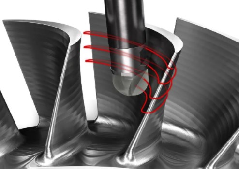
Machining a gap in each corner of the pocket is a less expensive option. It gets rid of the pesky radius, leaving a U- or C-shaped clearance in its place. It also makes for much deeper pockets—by cutting a 0.25 in, (6.35mm) broad relief in each corner, technically sharp corners with depths of up to 1-1/4 in. (32mm) are possible. Using aluminum or even plastic instead of steel, pocket depths that are twice as deep as steel is possible. The best part is that building pockets lower part cost because larger end mills can get used, and it can improve material removal speeds accordingly.
-
Deburr Edges Yourself
Another radius-related cost-cutting step is to avoid corner breaks. External component intersections are often smoothed with chamfers or corner radii to eliminate burrs and break sharp corners. It’s natural and usually even appropriate, but it can be costly. We provide automated deburring on metal parts, and plastics are supplied as-machined or with a sharp edge.
If the part design requires an edge split, we must use an additional tool (a ball end mill) to machine the corners with a 3D profiling motion. We usually run these tools at high rpm and extract tiny quantities of content, but it’s still a time-consuming process to go back and forth until each corner is smooth. Many consumers prefer to save money by deburring these parts themselves with a file, abrasive document, or a buffing wheel.
-
Avoid Text Until Molding
Similarly, text engraving is an aesthetically pleasing yet time-consuming process that should get avoided if possible. A ball end mill gets used to trace whatever letters, numbers, and symbols get defined on the CAD model. It looks great and may be a legitimate requirement for your machined component. Still, it’s probably more suitable for injection-molded products, where the extra CNC Prototype time gets amortized over higher part volumes. We have a minimum size of 0.90mm in metals and 0.51mm in plastics due to our tooling for metals vs. plastics.
-
Be Cautious of Thin Walls and Features
Our standard tolerance for parts is +/- 0.005 in (0.13mm). Suppose you have a feature that is 0.020 in. (0.51mm) or smaller. In that case, our automated quoting system will highlight it as thin-wall geometry but bear in mind that it can still be machined so that the machined component can vary slightly from your original design. Thin walls of 0.020 in. or less are not only prone to breakage during the prototyping process, but they can also flex or warp afterward. Increase their size as much as your component design requires.
-
Keep it Simple
Even if the corners are relieved, deep pockets are not permitted. Gussets or support systems can get used to support these workpieces and avoid stress-related movement, but these appear to increase machining costs. Keep it easy is the best advice for any Prototype Companies or machined component designer.
The same principle holds for overall component geometry. Don’t try to make parts do more than they need to. Maximizing material use can result in work holding or machining issues, raising costs. If the design becomes too complicated, consider breaking it down into different parts and assembling them with fasteners.
Nobody enjoys assembly costs or the complexity that comes with several components, but it might be the best solution for difficult-to-machine details if speed is a necessity. Sculptured surfaces, cavernous slots (think heatsinks), super deep holes (hydraulic manifolds), and threads are all popular Prototyping cost drivers that can eat into your project budget.
We hope these tips will help you save on the cost of CNC prototyping. Switching to a more machine-friendly or less costly material is one of the best ways to remain within budget (assuming it meets the requirements).


